
Choosing between a high-frequency inverter and a conventional DC resistance welding system should not be based only on equipment price, machine size, or the word “inverter.”
Both systems may deliver DC welding current, but they generate and control that current differently. For battery manufacturers, the practical difference lies in current response, waveform control, process feedback, monitoring capability, automation integration, and suitability for the actual weld joint.
A high-frequency inverter is often preferred when a battery welding application requires short and programmable weld schedules, closed-loop process control, production data, and stable integration into automated equipment. A conventional line-frequency rectified DC system may remain suitable for less demanding or more stable applications where simple operation and maintenance are the main priorities.
The final choice must still be confirmed according to the cell format, tab or busbar material, material thickness, joint structure, welding force, quality standard, and target production cycle.
Why This Comparison Matters in Battery Production
Battery resistance welding is not simply a matter of passing current through two metal parts.
The welding result is influenced by several interacting variables:
- Electrical current
- Weld time
- Electrode force
- Contact resistance
- Surface coating and cleanliness
- Electrode condition
- Material thickness and number of layers
- Joint geometry
- Fixture repeatability
- Heat dissipation
A power supply that is adequate for a stable, relatively simple joint may not provide enough process control for a thin battery tab, a multilayer connector, or a production line requiring traceability.
At the same time, selecting the most advanced power supply does not automatically solve an unsuitable joint design or inconsistent electrode pressure. The welding power supply, transformer, weld head, electrodes, fixture, and workpiece must operate as one process system.
Resistance welding power supplies are available in several technical categories, including high-frequency inverter, linear DC, capacitive discharge, and AC systems. High-frequency inverter and linear DC systems can both provide controlled output, but they use different power architectures and should not be treated as the same technology. (AMADA WELD TECH)
What Is a Conventional DC Resistance Welding System?
In this article, “conventional DC” refers specifically to a line-frequency transformer and rectifier-based resistance welding system.
A simplified operating sequence is:
- Incoming AC power enters a line-frequency transformer.
- The transformer reduces the voltage and increases the available welding current.
- A rectifier converts the transformer output into DC.
- The welding current is delivered through the secondary circuit, electrodes, and workpiece.
This type of system can offer a relatively straightforward electrical structure and may be durable in appropriate operating environments.
However, depending on the controller and equipment design, it may provide less flexibility in short weld-time adjustment, waveform shaping, high-speed feedback, production monitoring, and communication with automated equipment.
It is important not to confuse this category with transistor or linear DC resistance welding systems. Linear DC power supplies can provide fast and highly controlled welding output and are often used for precision micro-welding applications.
What Is a High-Frequency Inverter Resistance Welder?
A high-frequency inverter resistance welding power supply normally converts incoming AC power into DC and then uses electronic switching to create a high-frequency waveform. After voltage transformation and secondary rectification, controlled welding current is delivered to the electrodes.
The main procurement value of this architecture is not simply that the transformer can be smaller. Its more important advantage is the ability to support fast electronic control and feedback.
Depending on the equipment configuration, a high-frequency inverter may provide:
- Closed-loop current control
- Constant-current, constant-voltage, or constant-power modes
- Programmable weld schedules
- Multiple-stage or multi-pulse waveforms
- Current, voltage, resistance, or energy monitoring
- Weld-limit monitoring
- Data output for production records
- Interfaces for automation integration
High-frequency inverter systems are widely used where precise, programmable energy delivery and automation compatibility are required. However, the available control modes, feedback speed, monitoring functions, and output capacity vary by model and should be checked in the actual equipment specification. (AMADA WELD TECH)
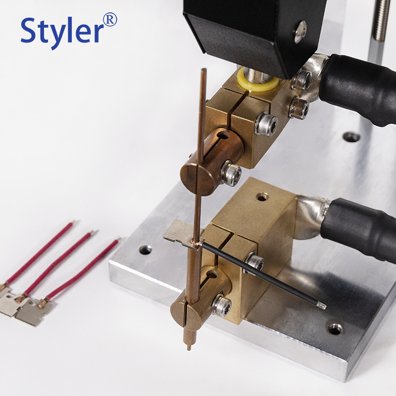
(Credit: Image from Styler)
Common Buyer and Engineering Pain Points
Battery manufacturers frequently encounter the following problems when comparing welding systems.
The two quotations use different technical terminology
One supplier may quote an inverter spot welder, while another quotes a transistor DC welder or a conventional DC resistance welder. The equipment names alone do not show whether the systems provide comparable control modes, output capability, weld heads, monitoring, tooling, or automation interfaces.
Sample welds look acceptable, but production results fluctuate
An initial sample may be produced under carefully controlled conditions. During continuous production, variations in material coating, electrode wear, fixture position, surface condition, and cell tolerance can affect weld consistency.
The current product uses thin nickel strip, but future products may use different connectors
A machine selected only for the current sample may not support a future change in material, thickness, number of layers, or weld geometry. Conversely, purchasing a much larger power supply does not guarantee that it will provide better control for a thin and heat-sensitive joint.
Buyers focus on maximum current
Maximum output is only one equipment parameter. Stable production also depends on minimum controllable output, current rise time, weld-time resolution, feedback mode, electrode force, secondary circuit design, and process repeatability.
The customer requests copper or aluminum welding without defining the joint
Material names alone are not enough to confirm feasibility. Copper and aluminum have different electrical, thermal, surface, and mechanical characteristics. Their weldability depends on the specific material combination, coating, thickness, joint design, heat balance, electrode access, and acceptable deformation.
Technical Decision Factors
Before choosing a high-frequency inverter or conventional DC resistance welding system, the buyer should provide the following information.
Battery and workpiece information
- Cell format and dimensions
- Cell terminal construction
- Tab, connector, or busbar material
- Surface plating or coating
- Individual layer thickness
- Total number of layers
- Joint overlap and weld location
- Electrode access direction
- Acceptable cell deformation
The equipment should not be selected only because the product uses an 18650, 21700, prismatic, or pouch cell. Two battery packs using the same cell format may require different welding systems because their connectors and joint structures are different.
Welding quality requirements
- Peel or pull-strength requirement
- Electrical resistance requirement
- Acceptable weld appearance
- Maximum spatter or indentation
- Heat-affected area limitation
- Cell temperature limitation
- Process consistency requirement
- Inspection and traceability requirements
Production requirements
- Required welds per product
- Target cycle time
- Daily or annual production volume
- Manual, semi-automatic, or automatic loading
- Product changeover frequency
- Required recipe storage
- Data-recording requirements
- PLC or MES communication
- Upstream and downstream integration
Factory and service requirements
- Available electrical supply
- Cooling requirements
- Compressed-air requirements
- Installation space
- Operator training
- Spare electrodes and consumables
- Preventive maintenance
- Local or remote technical support
Which System Is More Suitable?
A high-frequency inverter may be more suitable when:
- The welding schedule is short and requires fine adjustment.
- The application needs closed-loop current, voltage, or power control.
- The manufacturer processes several product models and needs stored recipes.
- Production requires weld monitoring and data output.
- The power supply must integrate with automatic feeding, positioning, inspection, or reject-handling systems.
- Variations in the secondary circuit need to be managed through faster feedback.
- The project requires a compact power supply for machine integration.
A conventional DC system may remain suitable when:
- The joint and material combination are stable and well established.
- The application does not require complex waveform programming.
- Production volume is relatively limited.
- Extensive data recording or automation communication is not required.
- Simple maintenance is a major operational priority.
- The required weld window has already been validated with the proposed system.
These are general selection principles rather than automatic recommendations.
A conventional system should not be rejected merely because it is older in design. Similarly, an inverter should not be selected merely because it provides more settings. Equipment capability must be matched to the actual process.
What About Transistor DC Welding?
Transistor DC, also known as linear DC in some equipment classifications, should be evaluated separately from conventional rectified DC.
Linear DC systems can provide fast response and precisely controlled short-duration weld pulses. Depending on the equipment, they may support constant-current, constant-voltage, or constant-power operation.
For precision battery tab welding, the relevant comparison may therefore be:
- High-frequency inverter
- Transistor or linear DC
- Capacitive discharge
- AC or other resistance welding power supplies
rather than simply “inverter versus DC.”
Both high-frequency inverter and transistorized systems have been used for miniature and precision resistance welding because feedback control can provide fine control of short welding pulses. (TWI Global)
Why Material Type Alone Cannot Determine the Equipment
Nickel, nickel-plated steel, copper, aluminum, and stainless steel do not respond identically to resistance welding.
Even within the same general material category, the result can change because of:
- Alloy composition
- Surface plating
- Oxide layers
- Material hardness
- Thickness tolerance
- Number of layers
- Contact area
- Electrode material
- Electrode geometry
- Welding force
- Heat dissipation
- Polarity
- Secondary circuit resistance
For example, a high-frequency inverter may provide useful process control for a conductive material, but that does not mean every copper or aluminum connector can be resistance welded successfully.
Some busbar or battery tab applications may be better suited to laser welding, ultrasonic welding, or another joining process. Feasibility should be determined through joint evaluation and sample testing.
Sample Testing and Process Validation
Sample testing is recommended before the final equipment configuration and quotation are confirmed.
The customer should normally provide:
- Actual battery cells
- Tabs, connectors, or busbars
- Material specifications
- Thickness information
- Drawings showing the joint structure
- Representative production samples
- Required weld locations
- Quality and inspection standards
- Target production cycle
Initial testing may evaluate:
- Weld appearance
- Peel strength
- Pull strength
- Electrical resistance
- Spatter
- Burn-through
- Electrode indentation
- Workpiece deformation
- Heat-affected area
- Cycle time
- Electrode wear
- Repeatability across multiple samples
A successful sample weld confirms only initial feasibility under the tested conditions. It does not automatically confirm continuous-production stability.
Pilot operation should also consider material tolerances, fixture accuracy, electrode maintenance, operator handling, production speed, and the number of consecutive welds.
Quality Control and Acceptance Criteria
Before placing an order, the buyer and equipment supplier should agree on measurable acceptance criteria.
These may include:
- Approved reference samples
- Test method for peel or pull strength
- Electrical resistance measurement method
- Acceptable weld appearance
- Maximum allowable spatter or deformation
- Target cycle time
- Continuous operating test duration
- Product changeover procedure
- Recipe-management requirements
- Weld-data recording
- Alarm and reject logic
- Electrode maintenance requirements
- Equipment safety provisions
- Factory Acceptance Test scope
- Site Acceptance Test scope
- Installation and training responsibilities
No responsible welding equipment supplier should promise zero defects or 100% production yield without clearly defined materials, operating conditions, inspection methods, and project validation.
Typical Application Scenarios
High-frequency inverter resistance welding may be evaluated for applications such as:
- Cylindrical battery nickel-strip welding
- Nickel-plated steel connector welding
- Consumer electronics battery packs
- Power tool battery packs
- E-bike and light electric vehicle battery packs
- Selected battery tab and terminal joints
- Automated battery pack welding stations
The process is not automatically suitable for every prismatic module, pouch cell tab, copper connector, aluminum busbar, or ESS battery component.
For these applications, the supplier should first review the actual material combination, joint structure, required weld area, electrode access, quality standard, and target production cycle.
Buyer Checklist
Before comparing resistance welding machine quotations, ask:
- What power supply technology is included in the quotation?
- What cell, tab, and connector materials will be processed?
- What are the thickness, coating, and number of material layers?
- Which output-control and feedback modes are available?
- What weld monitoring and data-recording functions are included?
- Are the weld head, transformer, electrodes, fixture, and cooling system included?
- Can the supplier conduct sample welding before final configuration?
- What quality standards will be used during FAT?
- What is the required production cycle and automation level?
- What installation, training, spare parts, and after-sales support are included?
Equipment quotations cannot be compared accurately unless the welding scope, tooling, control functions, automation requirements, testing methods, and acceptance standards are clearly defined.
Why Styler
Styler is a battery welding equipment manufacturer providing resistance welding, laser welding, and battery pack assembly solutions for battery production applications.
Rather than recommending equipment according to the battery model alone, Styler evaluates the welding material, joint structure, quality target, production cycle, operating method, and automation requirements.
Depending on the project scope, the evaluation may include:
- Welding process discussion
- Sample feasibility testing
- Welding power supply selection
- Weld head and electrode configuration
- Fixture development
- Semi-automatic equipment
- Automated battery pack assembly integration
- Production monitoring requirements
- Installation and training support
The final configuration should be confirmed after technical evaluation. Customization is based on project feasibility and defined acceptance criteria.
Frequently Asked Questions
Is an inverter welder always better than a conventional DC welder?
No. A high-frequency inverter generally provides more flexible control, monitoring, and automation options, but the better choice depends on the material, joint design, weld-time requirement, production volume, and acceptance standard.
Is an inverter resistance welder a DC welder?
Many high-frequency inverter resistance welding systems deliver rectified DC output to the welding electrodes. “Inverter” describes the internal power-conversion and control architecture, while “DC” describes the output-current form. The terms are therefore not necessarily opposites.
Can one inverter welder process different battery models?
Possibly, but feasibility depends on the materials, thicknesses, joint structures, required current range, weld head, electrodes, fixtures, and production method. Different products may require different tooling or even a different power supply.
Can copper and aluminum battery parts be resistance welded?
Some copper or aluminum joints may be technically feasible, but material names alone are insufficient to confirm the process. Sample testing and joint evaluation are required. Some applications may be better suited to laser or ultrasonic welding.
Is sample testing required before purchasing?
Sample testing is strongly recommended when the material combination, thickness, joint design, or quality requirement has not already been validated. Testing helps determine initial feasibility and equipment configuration, but continuous-production validation is still necessary.
Conclusion
The decision between a high-frequency inverter and a conventional DC resistance welding system should begin with the battery joint, not the equipment name.
First define the cell format, material combination, thickness, joint geometry, weld-strength requirement, electrical-resistance requirement, target cycle time, and automation scope.
Then evaluate which power supply, weld head, electrodes, fixture, and monitoring functions can meet those requirements.
A high-frequency inverter may provide valuable control and integration capabilities for precision battery welding, but it is not automatically the correct solution for every battery product. Sample testing and clearly defined acceptance criteria are essential before the equipment configuration is finalized.
Discuss Your Battery Welding Application
Send Styler your battery cells, welding materials, thickness specifications, drawings, quality requirements, and target production cycle.
Our team can review the application, discuss sample welding, and recommend a resistance welding or battery pack assembly solution based on the actual project requirements.
Website: www.stylerwelding.com
Email: sales4@styler.com.cn
WhatsApp: +86-15218784866
Post time: Aug-12-2026


